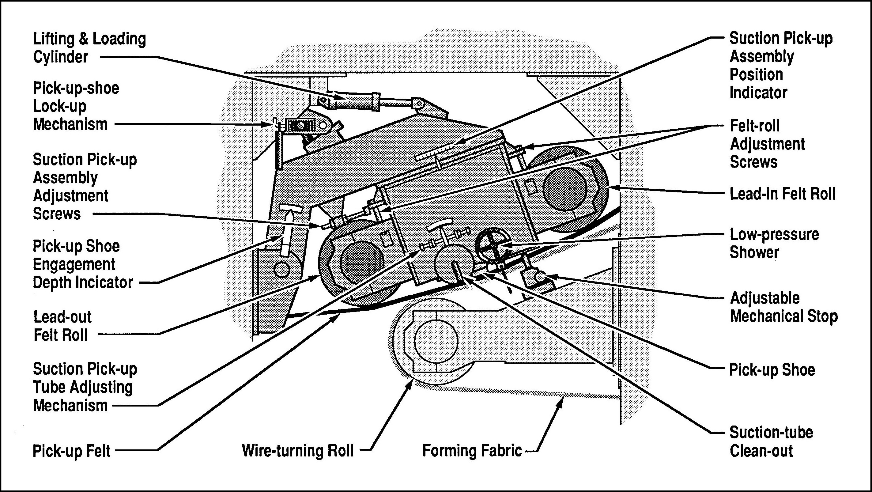
Technical Illustration
I think both verbally and visually in unison. I can envision and execute illustrations that support and clarify the text in technical documentation, and vice versa. I am adept at technical illustration – orthographic, axonometric, and two- and three-point perspective, cut-aways, and exploded views. I have generated illustrations on the traditional drawing board and on the computer using illustration, CAD, and solid-modeling software.
For the most part, technical illustration is
nonlinguistic communication. It is not based on any convention comprising a set of symbols or a set of rules governing the use of such symbols, the qualifying criteria of any language. Yet illustrations are capable of communicating quite effectively, in some cases more effectively than accompanying text, indeed, even in the absence of accompanying text altogether. Moreover, illustration transcends language; a clear illustration can communicate effectively for speakers of any language. For localization, only the callouts need to be translated.
There are rules for generating accurate technical illustrations, of course, but those rules do not entail the use of symbols or govern the use of symbols per se. Except for labels and callouts that may be added to an illustration, the elements in an illustration are not symbols. A symbol, such as a word, represents an object by means of convention. The relatioship between the graphic elements in an illustration to actual, physical objects is not dependent on any convention, however, but rather on the visual verisimilitude between those elements and the physical objects that they represent. Those elements copy the forms, contours, and geometric relationships that actually exist in the objects represented, and those relationships exist independently of any linguistic convention.
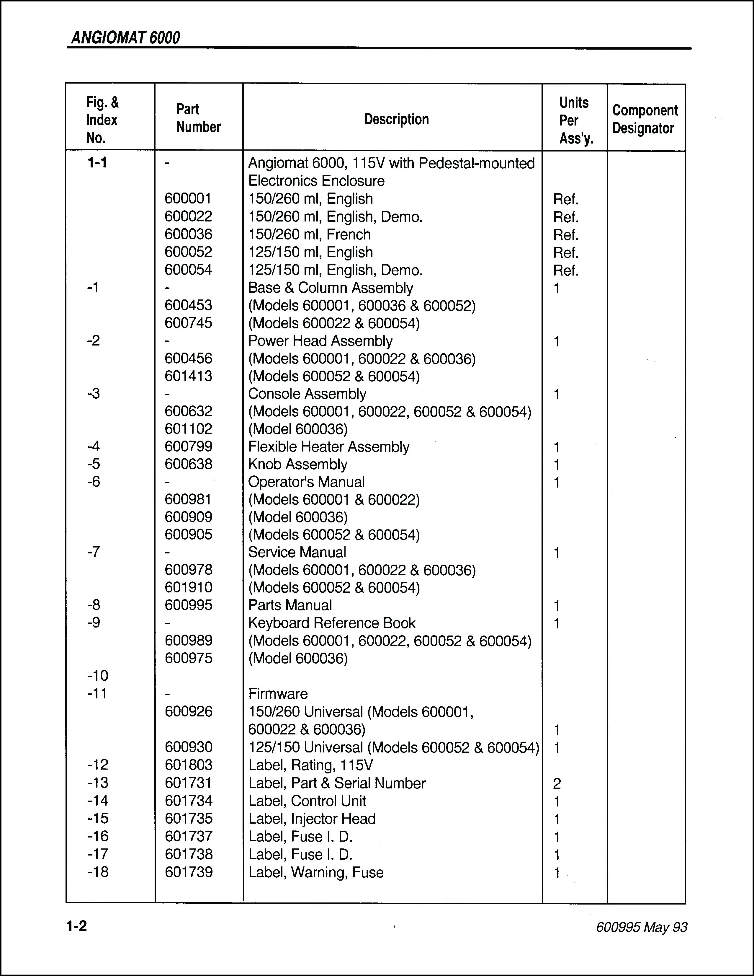
Scale
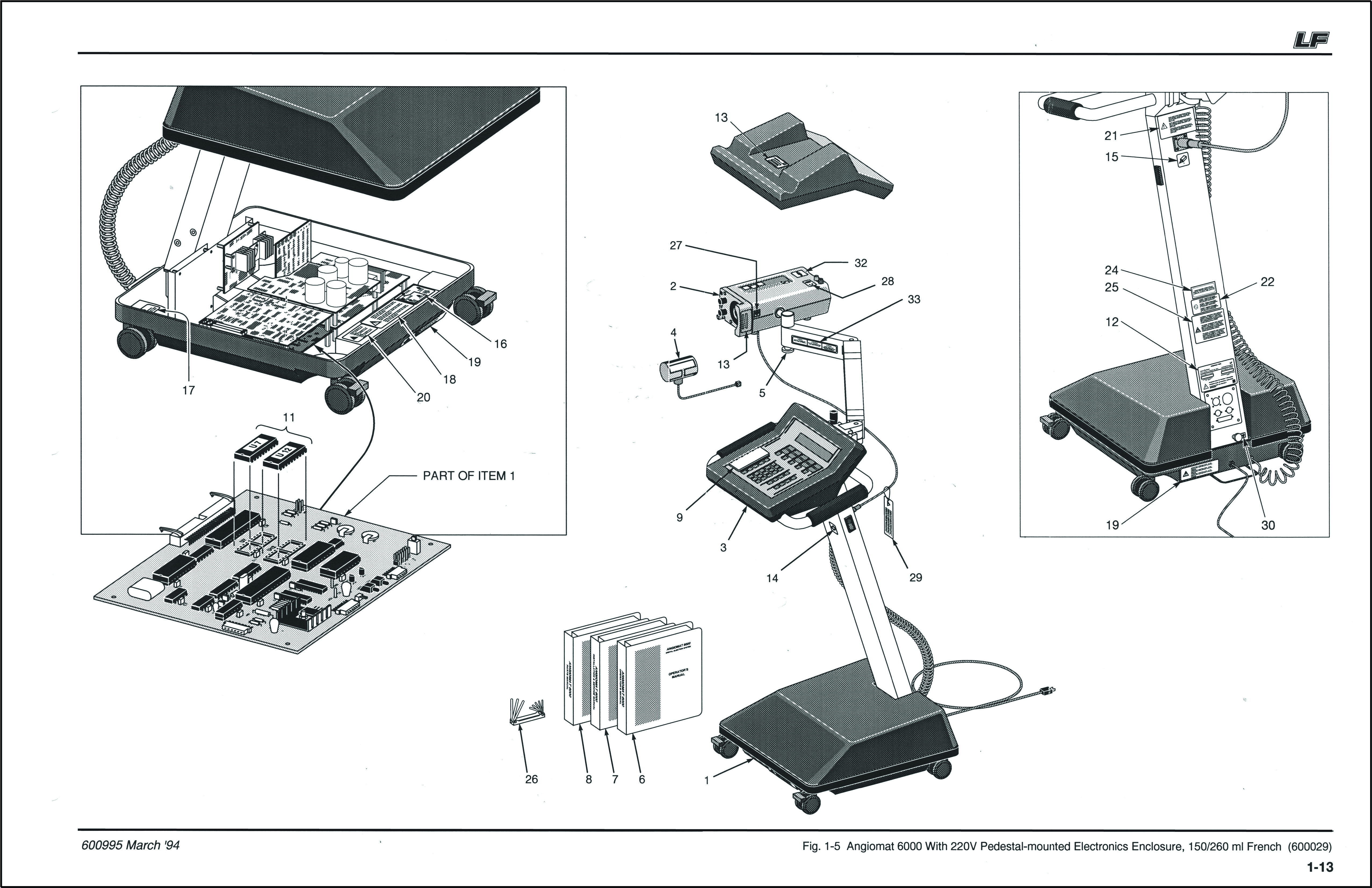
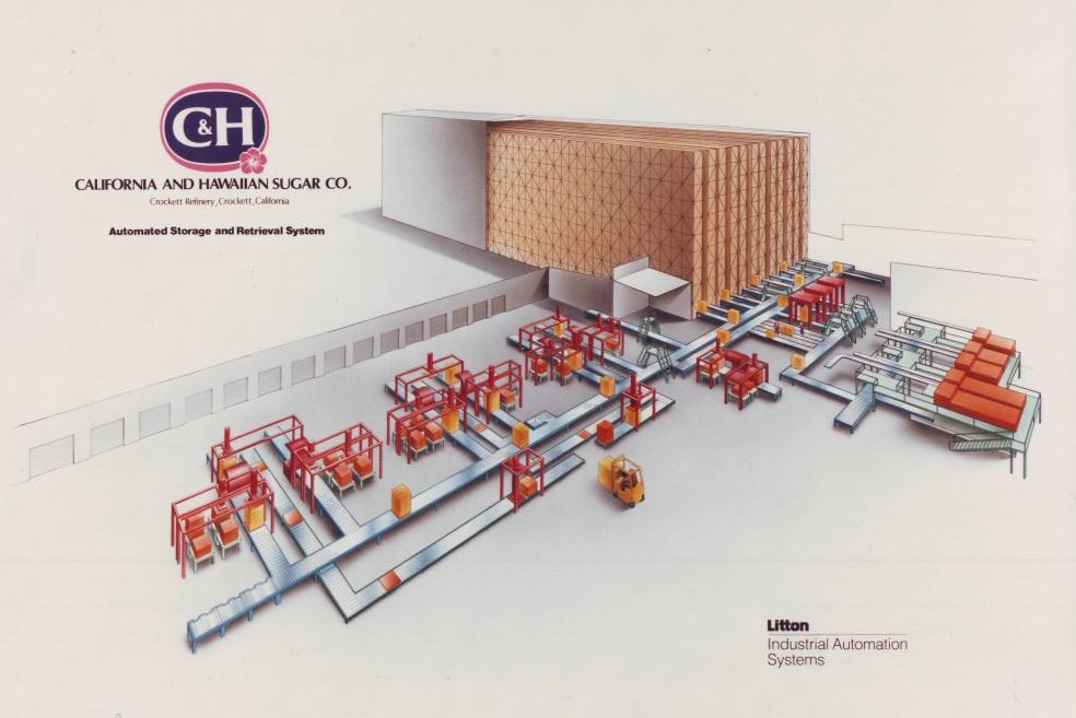
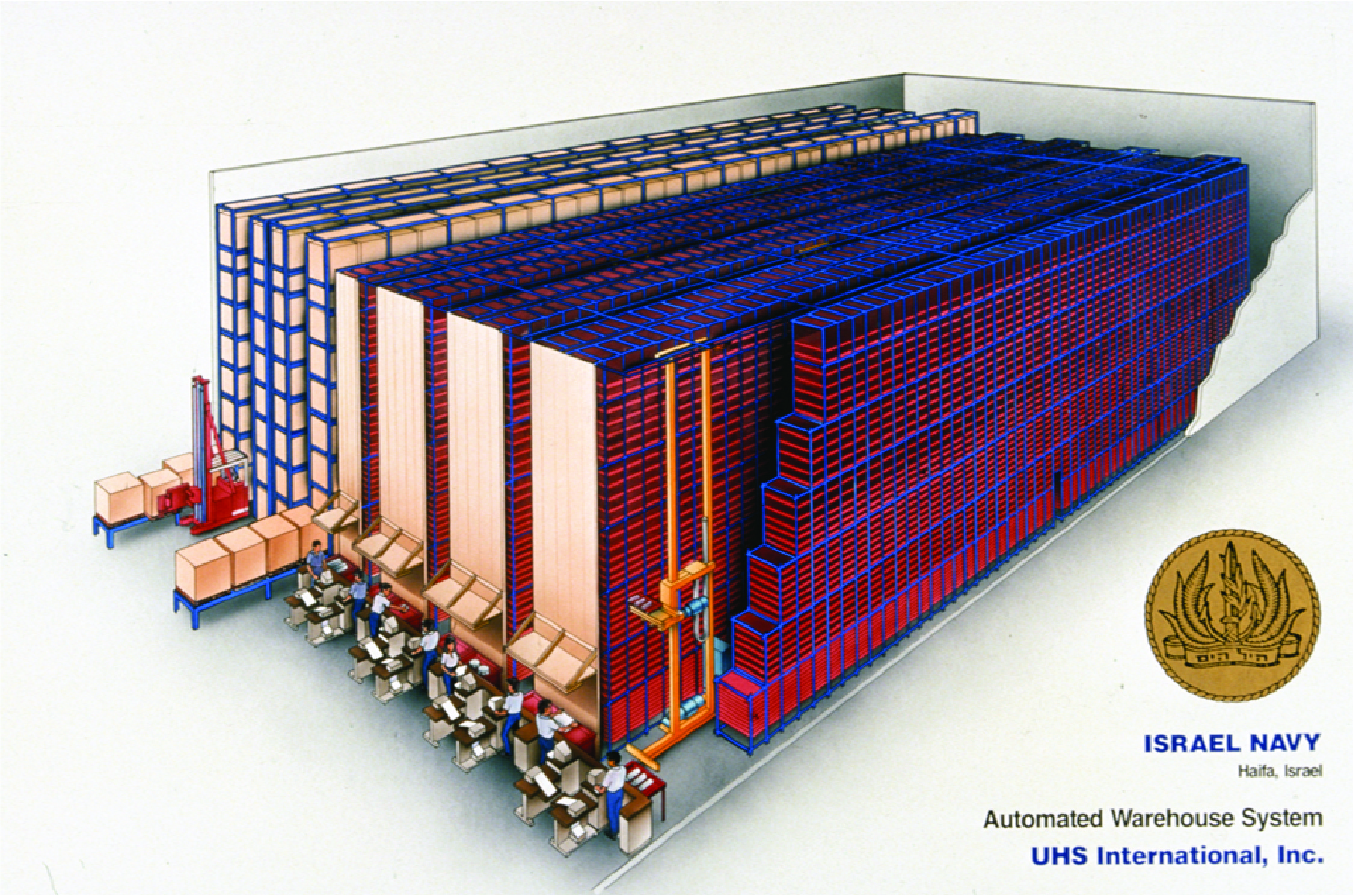
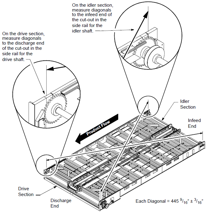
My illustrations are drawn precisely to scale,
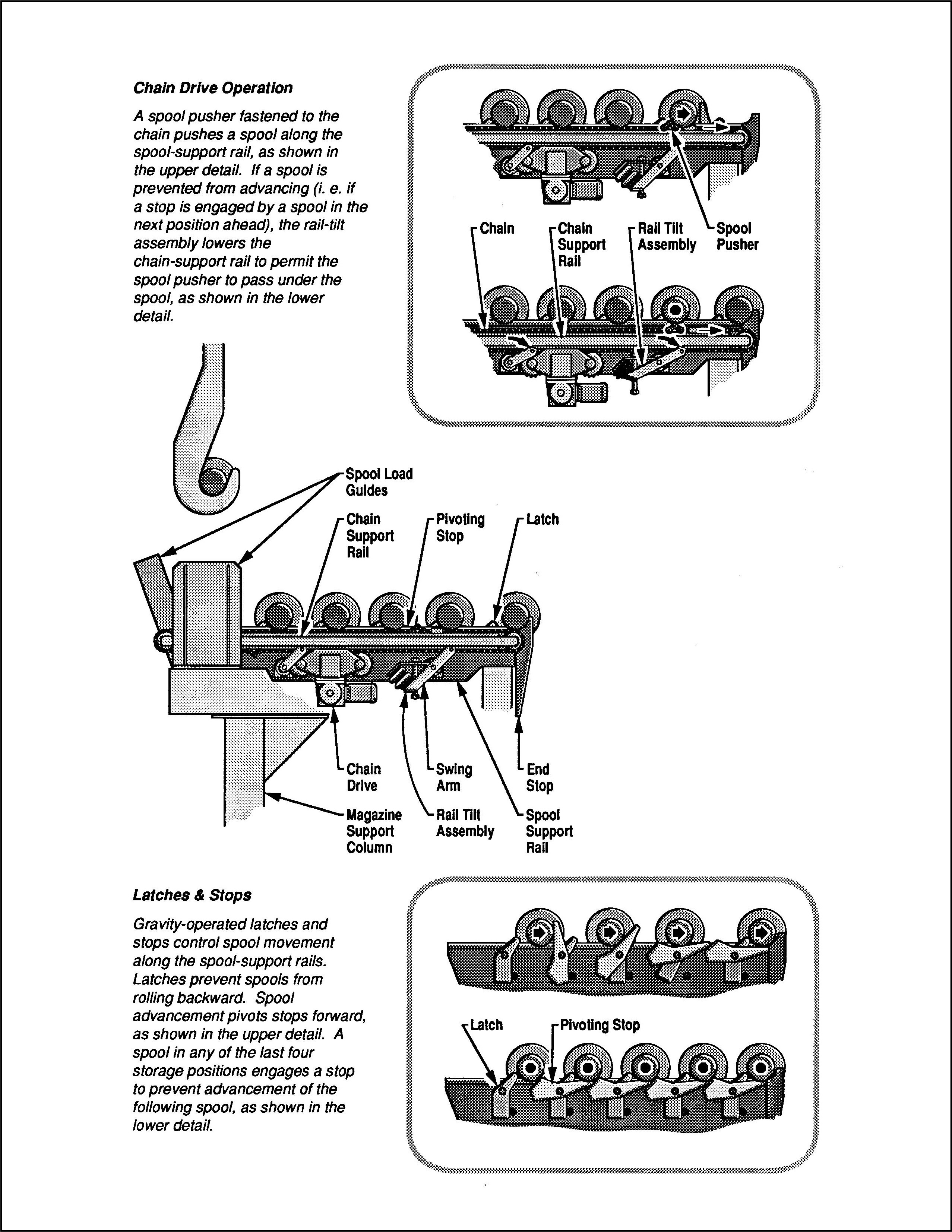
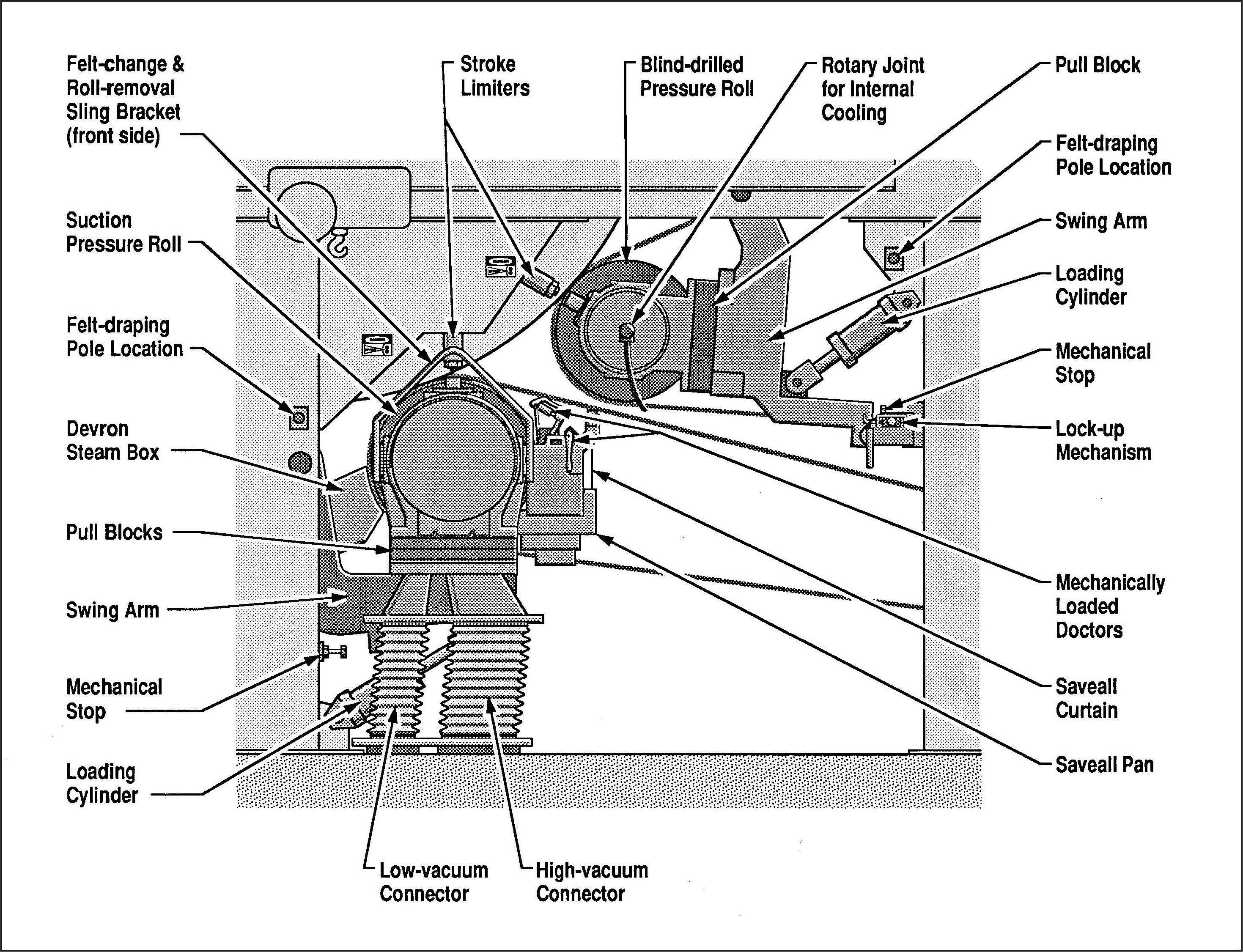
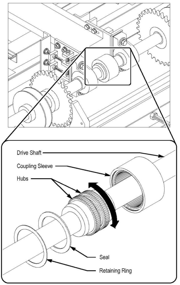
including perspective illustrations, grounded in the discipline of engineering drawing and drafting. I can work from engineering drawings or solid models, from photographs, or by taking measurements of physical objects. Depicting extremely large objects (such as paper-making machines or multi-section material-handling equipment) intelligibly on a letter-size page requires special graphic treatment. For example, I include "pop-out" detail drawings in order to show miniscule features in relation to the larger whole,
Navigation
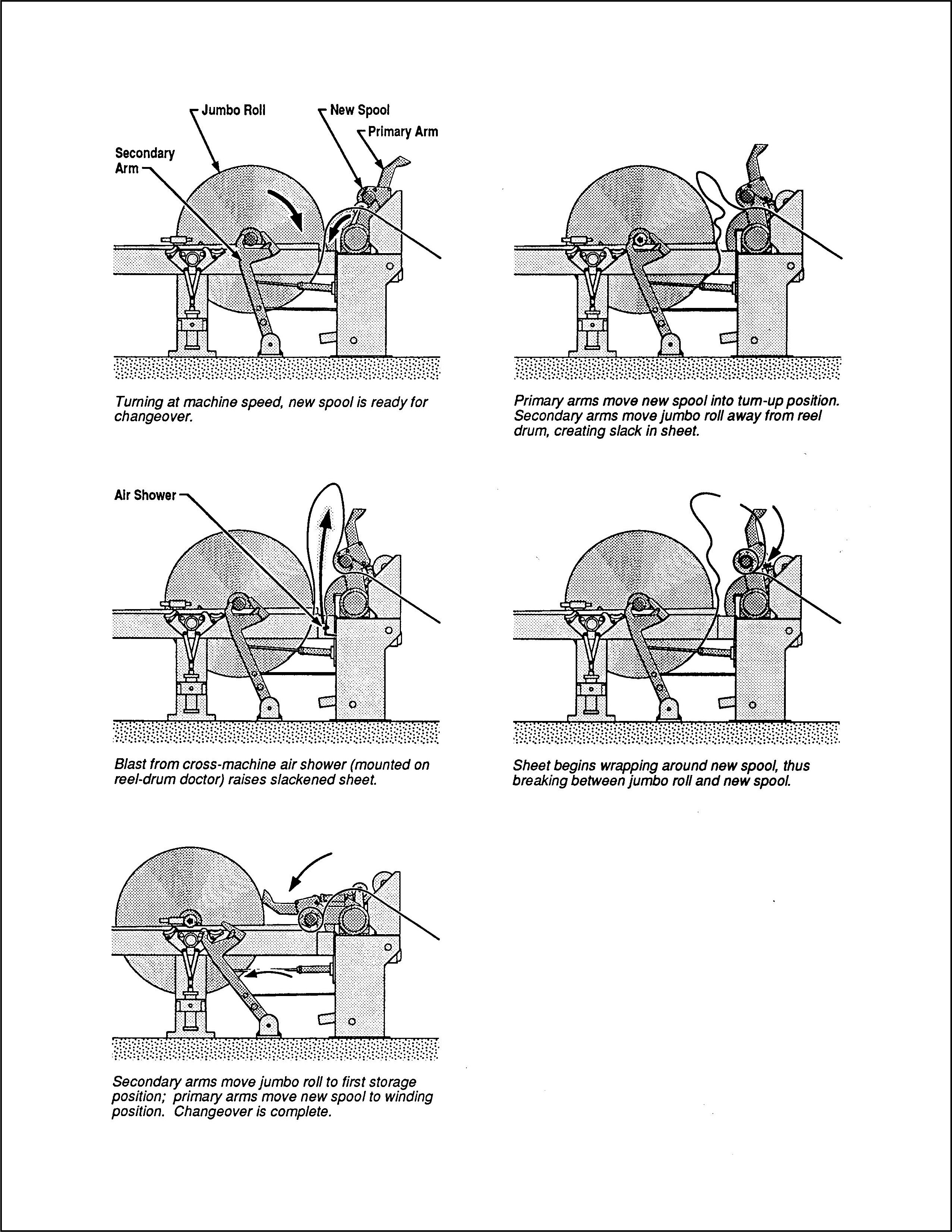
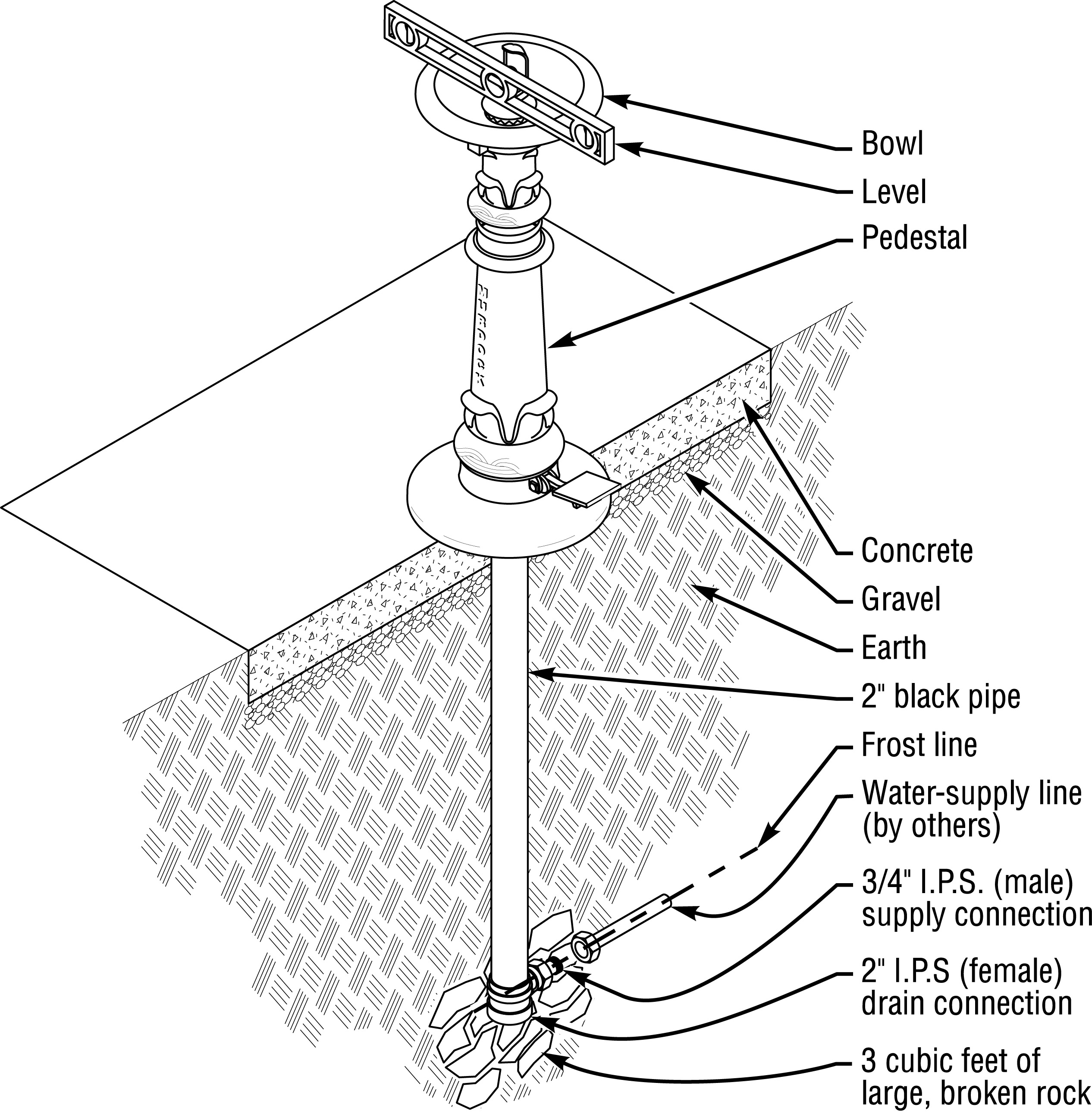
An end user can engage an illustration containing callouts in one of two directions, either beginning with the text that the illustration supports and referencing the illustration to identify the objects to which the callouts point, or beginning with the illustration itself and consulting the accompanying text for an explanation of the objects that are identified by the callouts. So, in keeping with Mayer’s
Cognitive Theory of Multimedia Learning, a technical illustration and the accompanying text should be developed together for effective engagement in either direction. Especially in a complex illustration, for example, callouts should be arranged along simple search paths, so that the eye of the end user does not have to hunt through the entire illustration searching for a specific callout.
Diagrams & Charts
Unlike realistic illustrations, diagrams are quasi-linguistic; they generally entail symbols that convey meaning as well as rules governing the use of those symbols. Diagrams should be laid out as simply as possible. Wiring diagrams for electronic assembly, for example, can be built progressively – showing a limited set of connections at each of several stages in order of assembly to avoid crossing wiring lines, making the diagrams much easier and faster to follow. Piping and instrumentation diagrams should likewise be laid out as simply as possible, and for the same reason. Judicious spacing and alignment help to make a diagram intelligible.